Serving sailors online since 1997
Hunter OEM Parts
General Marine Parts
Hunter 34 Yanmar 3GMF Engine Data project with Noland Engineering RS11
posted 09-11-2020 by pa391as
Click for larger view
This project describes an upgrade completed recently on our 1985 Hunter 34. The goal of the project was to gather engine data from the Yanmar 3GMF engine, put this data on the existing sailboat network, and display the data on various displays. A secondary goal was not to disrupt or displace any of the existing engine alarms, but rather add digital telemetry in parallel. This seemed like a prudent approach; having a backup that you knows work is wise.
The thought of gathering digital data from a 1985 engine seemed like a tall and perhaps impossible request, however after some research I discovered it was surprisingly straightforward due to some forward thinking by the Yanmar engineers and readily available digital electronics equipment.
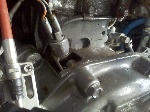
First, let’s start with the engine. The standard Yanmar 3GMF engine has sensors for engine RPM, fresh water coolant temperature, and lubricating oil pressure. The engine RPM sensor is mounted on the flywheel casing between the main engine and the transmission. It has two wires that connect with the wiring bus which makes its way to the engine console in the cockpit. The wiring can also be accessed behind a panel in the aft berth.
Staying true to the project goal of not dismantling any of the existing “idiot lights” or sensors, I wanted to leave the flywheel engine RPM sensor in place. Another source of engine RPM is the alternator. The PO had installed a Balmar 95 series alternator with external BRS regulator. The white wire on the back of the alternator sends electrical pulses from the AC stator. However, when putting a multimeter on this wire, it sensed no voltage. Long story short, the excellent technical support team at Balmar helped me diagnose a bad external regulator. Off to West Marine for a price-matched replacement regulator, and we’re back in business.
One quick note about the white wire, although not show in this picture, on these regulators it is important to route the white wire through the regulator. This ensure stator output even when he batteries are fully changed and the field is reduced. If you connect the white wire directly, bypassing the regulator, when the alternator stops outputting power to the batteries, it will also stop sending stator AC output and engine RPM will show 0.
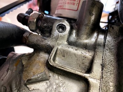
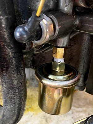
The fresh water coolant sensor is actually a temperature activated switch. It is located top forward of the engine near the thermostat and water pump assembly. In the picture, it is the lower of the two sensors. This is where Yanmar’s forward thinking comes into play. The bored a hole in the elbow that routes cooling water from the thermostat to the heat exchange ostensibly for an external water temperature gauge. Conveniently, this port can be used to mount a resistive temperature sender, shown in the picture. The analog temperature gauge affixed with duct tape was used for calibration, more on that later.
The temperature sender can be procured here:
https://www.catalinadirect.com/shop-by-boat/catalina-380390/electrical/temperature-sender-yanmar-diesels/
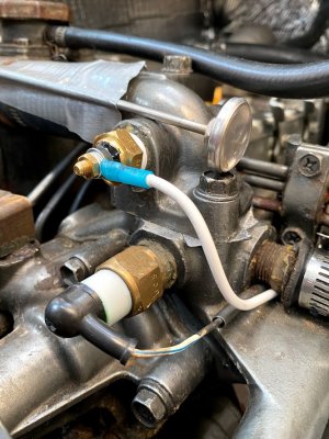
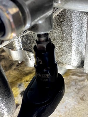
Next up is the engine lubricating oil pressure sensor. Same situation, Yanmar added an extra port for an external oil pressure gauge. First, you must remove the plug. For me, the coolant water plug was removed with some excess force, but otherwise no problem. The oil pressure plug, not so much. Not sure exactly why this oil plug was different, but it would not budge, and I ended up stripping the hex plug.
No problem though, Amazon sells an set of extractors for $39. Not sure when I’ll need these again, but a nice addition to the toolbox nonetheless!
https://www.amazon.com/gp/product/B07YBWNCZV/ref=ppx_yo_dt_b_asin_title_o00_s00?ie=UTF8 and psc=1
With the proper tool, the plug came right out, no problem.
Note: when installing the senders, do NOT use pipe tape! A clean connection between metals must be had as these are resistive senders.
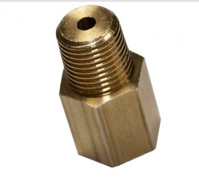
For the oil pressure sender, an adapter is required because a thread differences between the Yanmar (British Standard Pipe Thread) and the sender (NTP)
This adapter makes the conversion from 1/8 BSPT Male to 1/8-27 NPT Female:
https://www.amazon.com/gp/product/B00NWZ3TUI/ref=ppx_yo_dt_b_asin_title_o00_s00?ie=UTF8 and psc=1
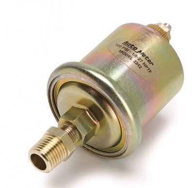
Once the adapter is installed, this sensor is installed. The oil pressure sender comes with an adapter, which is removed before installation.
https://www.amazon.com/gp/product/B00062YVIY/ref=ppx_yo_dt_b_asin_title_o00_s01?ie=UTF8 and psc=1
Once installed, it looks like this:
Disregard the pipe tape...I installed the sender before reading the instructions in the RS11 that indicated not to use pipe tape! :-)
Ok, that takes care of the senders.
I also wanted to capture and display battery voltage, battery current, and engine hours. Our boat has a standard 1/2/Off/All battery switch that is located to port of the refrigerator with the back containing the posts inside the engine compartment.
Being a fan of the fewest connections physically connected to the battery posts, I decided to run wire from the battery switch inputs to the RS11. On our sailboat, we have two batteries: House and Starter.
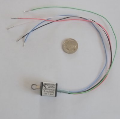
We also have a current shunt directly upstream of the ground connection to the engine housing. This requires a Noland Engineering AD50 Differential Amplifier to work properly.
https://www.nolandeng.com/ad50.php
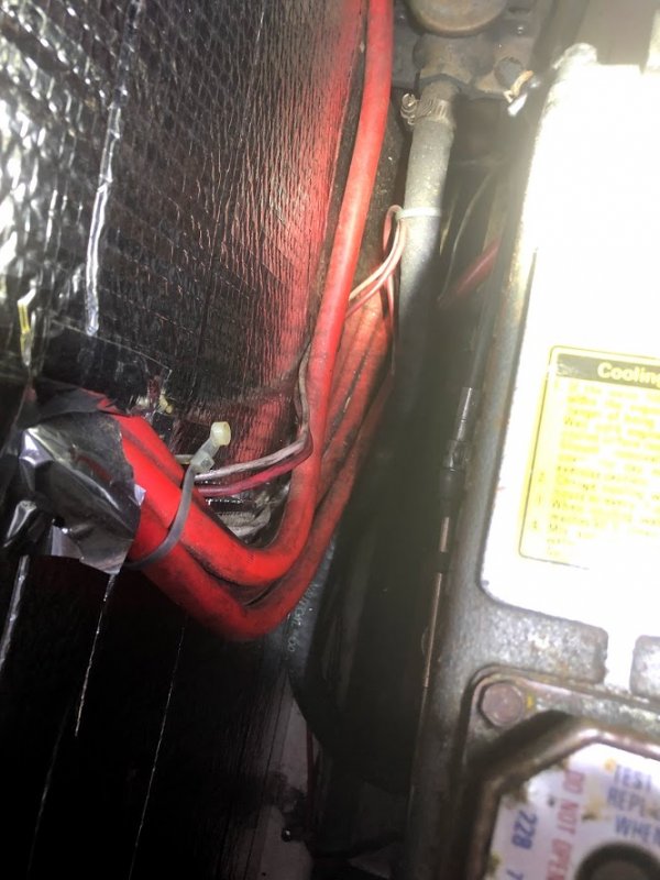
All the wiring from the battery switch, shunt, oil pressure sender, coolant temperature sender and alternator/regulator were all run inside the engine compartment, sealed with shrink wrap, and protected with wire wrap. The 3 senders (oil, temp, rpm) were all routed -tightly - within the existing wire wrap that goes from the engine compartment to the behind the engine console, which is accessible from the bulkhead in the aft berth.
(add picture)
The battery and shunt wires were routed after, up, underneath the pedestal, and over to the compartment behind the engine console. This is also where I installed the RS11. In order to make wiring easier, I used a terminal block. Power for the RS/11 and AD50 was routed from the engine console compartment aft to the back of the shore power outlet, then to port, and forward along with chase to the nav panel. Along this path was also routed the NMEA2000 cabling. Our boat has an existing Raymarine SeaTalkNG network, which is essentially NMEA2000 with proprietary (cough, cough, expensive) connectors. Since the RS11 has a NMEA2000 connector, I purchased an adapter
https://www.amazon.com/gp/product/B00L96X6W8/ref=ppx_yo_dt_b_asin_title_o09_s00?ie=UTF8 and psc=1
In addition, I had run out of spur ports, so I need an expansion backbone connector and another cable to connect it to the existing backbone.
https://www.amazon.com/gp/product/B00KIUAOBC/ref=ppx_yo_dt_b_asin_title_o09_s01?ie=UTF8 and psc=1
https://www.amazon.com/gp/product/B000WOHMDW/ref=ppx_yo_dt_b_asin_title_o09_s01?ie=UTF8 and psc=1
Once all of these cables are connected, the RS11 is now part of the NMEA2000/SeaTalkNG network.
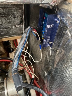
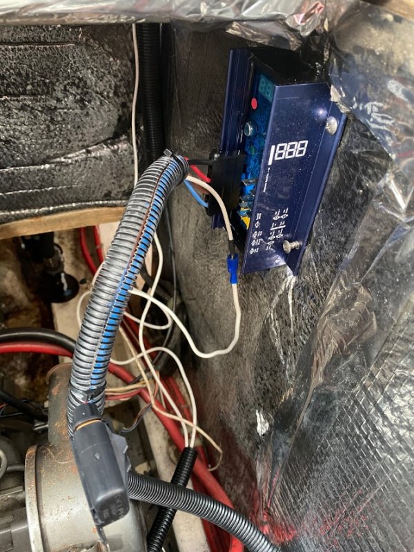
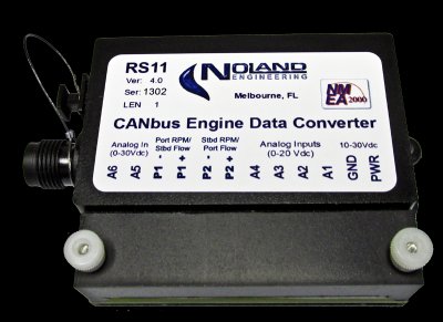
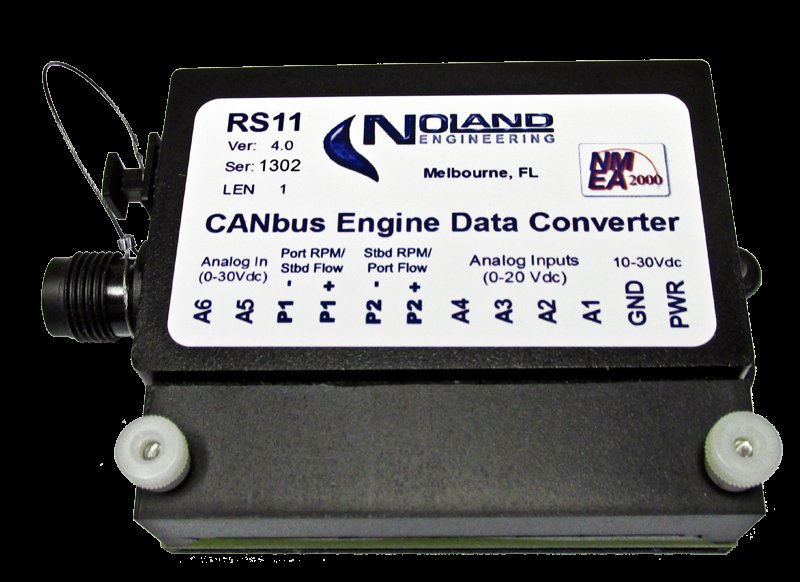
Ok. All of the wiring and sensors are in place. Now, to the RS11, which is the centerpiece of the project. The RS11 is made by Noland Engineering, which has excellent technical support! Brian from Noland was extremely helpful, providing advice, calibration values for known sensors, and great support throughout the project.
https://www.nolandeng.com/rs11.php
Cabling the RS11 is very simple. Power and Ground were supplied from a breaker in the nav panel. You will need to make a decision whether to power the RS11 from a new unused breaker, or terminal block it with an existing breaker. In our case the sailboat also has a ShipModul MiniPlex-3Wi-N2K, which is a NMEA2000/NMEA0183 bi-directional gateway with a wireless access point (or client on an existing WLAN).
http://www.shipmodul.com/en/miniplex-3.html#mpx3wi
Because the engine data will be broadcast over the wireless network, we used the same breaker as the devices function at the same time and one is dependent on the other.
P1+ connects to the white wire from the alternator/regulator
A1 connects to the fresh water coolant temperature sender
A2 connects to the oil pressure sender
A3 connects AD50
A5 connects to Battery #0 (Starter)
A6 connects to Battery #1 (House)
Once all the connections are made, you simply plug the RS11 into a PC with the supplied USB cable, install drivers, and launch the configuration program. You must then calibrate the unit. Noland Engineering was very helpful making recommendations for configurations values, however there is definitely some trial and error involved. I found it useful to confirm the values using an independent source.
For engine RPM, calibrating it requires knowing a value for your alternator. In our case, we discovered that the analog tachometer is not calibrated properly, which explains why the Yanmar was maxing out at 2500 RPM! Another to-do to recalibrate or replace the analog tach.
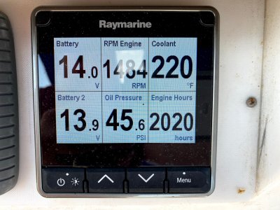
Once everything is calibrated, we setup a custom page on our Raymarine i70r display and here are the results. Engine hours are entered manually, and increment as long as the RS11 is powered while the engine is running, sensing RPMs.
The RS11 outputs CAN messages natively on the NMEA2000 (SeaTalkNG) network, so all devices on that network will natively display this data. It gets a little more tricky if you want to display the data on the NMEA0183 network. First, you will need a device which converts the NMEA2000 PGNs (Parameter Group Name) to NMEA0183 sentences. Our ShipModul Miniplex converts the messages properly, however whatever software or display you are using to display the data must be able to decipher the NMEA0183 sentences properly. In our case, we use OpenCPN with the engine data plug-in
https://github.com/TwoCanPlugIn/EngineDashboard
https://www.cruisersforum.com/forums/f134/engine-dashboard-plugin-226092.html
Uses a different method to decipher the transducer ID, which conflicts with how the sentences are transmitted on the bus. Another plug-in, the NMEA Converter
https://opencpn.org/OpenCPN/plugins/nmeaconvert.html
Is helpful in converting the NMEA0183 payload to display in OpenCPN properly. With this NMEA0183 input data
$ERRPM,E,0,2324.00,,A*69
$ERXDR,P,4.04,B,ENGOILP0,C,75.25,C,ENGTEMP0,G,2024.1,,ENGHRS0*01
$ERXDR,U,13.75,V,BATVOLT0,I,0.8,A,BATCURR0*4D
$ERXDR,U,13.27,V,BATVOLT1*14
And this code in the NMEA Converter plug-in,
$IIXDR,T,$ERRPM3,R,MAIN
$IIXDR,P,$ERXDR?P2*100000,P,MAIN
$IIXDR,C,$ERXDR?P6,C,MAIN
$IIXDR,G,$ERXDR?P10,H,MAIN
$IIXDR,U,$ERXDR?U??????????????????I2,V,HOUS
$IIXDR,U,$ERXDR?U??????????????????I6,A,STRT
$IIXDR,U,$ERXDR?U???????V?BATVOLT12,V,STRT
I’m able to see all but BATVOLT1 data. Still working on this….
The thought of gathering digital data from a 1985 engine seemed like a tall and perhaps impossible request, however after some research I discovered it was surprisingly straightforward due to some forward thinking by the Yanmar engineers and readily available digital electronics equipment.
First, let’s start with the engine. The standard Yanmar 3GMF engine has sensors for engine RPM, fresh water coolant temperature, and lubricating oil pressure. The engine RPM sensor is mounted on the flywheel casing between the main engine and the transmission. It has two wires that connect with the wiring bus which makes its way to the engine console in the cockpit. The wiring can also be accessed behind a panel in the aft berth.
Staying true to the project goal of not dismantling any of the existing “idiot lights” or sensors, I wanted to leave the flywheel engine RPM sensor in place. Another source of engine RPM is the alternator. The PO had installed a Balmar 95 series alternator with external BRS regulator. The white wire on the back of the alternator sends electrical pulses from the AC stator. However, when putting a multimeter on this wire, it sensed no voltage. Long story short, the excellent technical support team at Balmar helped me diagnose a bad external regulator. Off to West Marine for a price-matched replacement regulator, and we’re back in business.
One quick note about the white wire, although not show in this picture, on these regulators it is important to route the white wire through the regulator. This ensure stator output even when he batteries are fully changed and the field is reduced. If you connect the white wire directly, bypassing the regulator, when the alternator stops outputting power to the batteries, it will also stop sending stator AC output and engine RPM will show 0.
The fresh water coolant sensor is actually a temperature activated switch. It is located top forward of the engine near the thermostat and water pump assembly. In the picture, it is the lower of the two sensors. This is where Yanmar’s forward thinking comes into play. The bored a hole in the elbow that routes cooling water from the thermostat to the heat exchange ostensibly for an external water temperature gauge. Conveniently, this port can be used to mount a resistive temperature sender, shown in the picture. The analog temperature gauge affixed with duct tape was used for calibration, more on that later.
The temperature sender can be procured here:
https://www.catalinadirect.com/shop-by-boat/catalina-380390/electrical/temperature-sender-yanmar-diesels/
Next up is the engine lubricating oil pressure sensor. Same situation, Yanmar added an extra port for an external oil pressure gauge. First, you must remove the plug. For me, the coolant water plug was removed with some excess force, but otherwise no problem. The oil pressure plug, not so much. Not sure exactly why this oil plug was different, but it would not budge, and I ended up stripping the hex plug.
No problem though, Amazon sells an set of extractors for $39. Not sure when I’ll need these again, but a nice addition to the toolbox nonetheless!
https://www.amazon.com/gp/product/B07YBWNCZV/ref=ppx_yo_dt_b_asin_title_o00_s00?ie=UTF8 and psc=1
With the proper tool, the plug came right out, no problem.
Note: when installing the senders, do NOT use pipe tape! A clean connection between metals must be had as these are resistive senders.
For the oil pressure sender, an adapter is required because a thread differences between the Yanmar (British Standard Pipe Thread) and the sender (NTP)
This adapter makes the conversion from 1/8 BSPT Male to 1/8-27 NPT Female:
https://www.amazon.com/gp/product/B00NWZ3TUI/ref=ppx_yo_dt_b_asin_title_o00_s00?ie=UTF8 and psc=1
Once the adapter is installed, this sensor is installed. The oil pressure sender comes with an adapter, which is removed before installation.
https://www.amazon.com/gp/product/B00062YVIY/ref=ppx_yo_dt_b_asin_title_o00_s01?ie=UTF8 and psc=1
Once installed, it looks like this:
Disregard the pipe tape...I installed the sender before reading the instructions in the RS11 that indicated not to use pipe tape! :-)
Ok, that takes care of the senders.
I also wanted to capture and display battery voltage, battery current, and engine hours. Our boat has a standard 1/2/Off/All battery switch that is located to port of the refrigerator with the back containing the posts inside the engine compartment.
Being a fan of the fewest connections physically connected to the battery posts, I decided to run wire from the battery switch inputs to the RS11. On our sailboat, we have two batteries: House and Starter.
We also have a current shunt directly upstream of the ground connection to the engine housing. This requires a Noland Engineering AD50 Differential Amplifier to work properly.
https://www.nolandeng.com/ad50.php
All the wiring from the battery switch, shunt, oil pressure sender, coolant temperature sender and alternator/regulator were all run inside the engine compartment, sealed with shrink wrap, and protected with wire wrap. The 3 senders (oil, temp, rpm) were all routed -tightly - within the existing wire wrap that goes from the engine compartment to the behind the engine console, which is accessible from the bulkhead in the aft berth.
(add picture)
The battery and shunt wires were routed after, up, underneath the pedestal, and over to the compartment behind the engine console. This is also where I installed the RS11. In order to make wiring easier, I used a terminal block. Power for the RS/11 and AD50 was routed from the engine console compartment aft to the back of the shore power outlet, then to port, and forward along with chase to the nav panel. Along this path was also routed the NMEA2000 cabling. Our boat has an existing Raymarine SeaTalkNG network, which is essentially NMEA2000 with proprietary (cough, cough, expensive) connectors. Since the RS11 has a NMEA2000 connector, I purchased an adapter
https://www.amazon.com/gp/product/B00L96X6W8/ref=ppx_yo_dt_b_asin_title_o09_s00?ie=UTF8 and psc=1
In addition, I had run out of spur ports, so I need an expansion backbone connector and another cable to connect it to the existing backbone.
https://www.amazon.com/gp/product/B00KIUAOBC/ref=ppx_yo_dt_b_asin_title_o09_s01?ie=UTF8 and psc=1
https://www.amazon.com/gp/product/B000WOHMDW/ref=ppx_yo_dt_b_asin_title_o09_s01?ie=UTF8 and psc=1
Once all of these cables are connected, the RS11 is now part of the NMEA2000/SeaTalkNG network.
Ok. All of the wiring and sensors are in place. Now, to the RS11, which is the centerpiece of the project. The RS11 is made by Noland Engineering, which has excellent technical support! Brian from Noland was extremely helpful, providing advice, calibration values for known sensors, and great support throughout the project.
https://www.nolandeng.com/rs11.php
Cabling the RS11 is very simple. Power and Ground were supplied from a breaker in the nav panel. You will need to make a decision whether to power the RS11 from a new unused breaker, or terminal block it with an existing breaker. In our case the sailboat also has a ShipModul MiniPlex-3Wi-N2K, which is a NMEA2000/NMEA0183 bi-directional gateway with a wireless access point (or client on an existing WLAN).
http://www.shipmodul.com/en/miniplex-3.html#mpx3wi
Because the engine data will be broadcast over the wireless network, we used the same breaker as the devices function at the same time and one is dependent on the other.
P1+ connects to the white wire from the alternator/regulator
A1 connects to the fresh water coolant temperature sender
A2 connects to the oil pressure sender
A3 connects AD50
A5 connects to Battery #0 (Starter)
A6 connects to Battery #1 (House)
Once all the connections are made, you simply plug the RS11 into a PC with the supplied USB cable, install drivers, and launch the configuration program. You must then calibrate the unit. Noland Engineering was very helpful making recommendations for configurations values, however there is definitely some trial and error involved. I found it useful to confirm the values using an independent source.
For engine RPM, calibrating it requires knowing a value for your alternator. In our case, we discovered that the analog tachometer is not calibrated properly, which explains why the Yanmar was maxing out at 2500 RPM! Another to-do to recalibrate or replace the analog tach.
Once everything is calibrated, we setup a custom page on our Raymarine i70r display and here are the results. Engine hours are entered manually, and increment as long as the RS11 is powered while the engine is running, sensing RPMs.
The RS11 outputs CAN messages natively on the NMEA2000 (SeaTalkNG) network, so all devices on that network will natively display this data. It gets a little more tricky if you want to display the data on the NMEA0183 network. First, you will need a device which converts the NMEA2000 PGNs (Parameter Group Name) to NMEA0183 sentences. Our ShipModul Miniplex converts the messages properly, however whatever software or display you are using to display the data must be able to decipher the NMEA0183 sentences properly. In our case, we use OpenCPN with the engine data plug-in
https://github.com/TwoCanPlugIn/EngineDashboard
https://www.cruisersforum.com/forums/f134/engine-dashboard-plugin-226092.html
Uses a different method to decipher the transducer ID, which conflicts with how the sentences are transmitted on the bus. Another plug-in, the NMEA Converter
https://opencpn.org/OpenCPN/plugins/nmeaconvert.html
Is helpful in converting the NMEA0183 payload to display in OpenCPN properly. With this NMEA0183 input data
$ERRPM,E,0,2324.00,,A*69
$ERXDR,P,4.04,B,ENGOILP0,C,75.25,C,ENGTEMP0,G,2024.1,,ENGHRS0*01
$ERXDR,U,13.75,V,BATVOLT0,I,0.8,A,BATCURR0*4D
$ERXDR,U,13.27,V,BATVOLT1*14
And this code in the NMEA Converter plug-in,
$IIXDR,T,$ERRPM3,R,MAIN
$IIXDR,P,$ERXDR?P2*100000,P,MAIN
$IIXDR,C,$ERXDR?P6,C,MAIN
$IIXDR,G,$ERXDR?P10,H,MAIN
$IIXDR,U,$ERXDR?U??????????????????I2,V,HOUS
$IIXDR,U,$ERXDR?U??????????????????I6,A,STRT
$IIXDR,U,$ERXDR?U???????V?BATVOLT12,V,STRT
I’m able to see all but BATVOLT1 data. Still working on this….
Click for larger view
replacement Alternator external regulator installed and cabled
Click for larger view

New fresh water coolant sender installed.
Click for larger view

stripped the plug

Click for larger view

right tool for the right job
Click for larger view

plug came right out with the extractor
Click for larger view

adapter
Click for larger view

oil pressure sender
Click for larger view

oil sender installed

Click for larger view
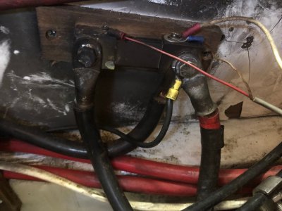
back of battery switch in engine compartment
Click for larger view

AD50
Click for larger view

current shunt
Click for larger view
RS11
Click for larger view

project finished. time for cold adult beverage!