Serving sailors online since 1997
Hunter OEM Parts
General Marine Parts
H-170 Motor Mount Fix Part 2
posted 11-04-2017 by JimInPB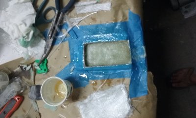
Click for larger view
This is a continuation of my repair to a bad motor mount on an H-170. The original article did not let me upload anymore pictures after #7, so I started a new article and called it part 2.
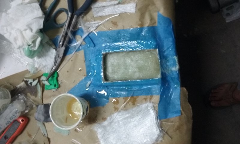
This picture shows almost 1/2 of glass that has been added above the green urethane foam. The glass is an alternating pile of mat and roving. I did it in a few batches. I only did 3 layers on the first pass, to minimize the risk of reaction heat damaging the foam.
This picture shows almost 1/2 of glass that has been added above the green urethane foam. The glass is an alternating pile of mat and roving. I did it in a few batches. I only did 3 layers on the first pass, to minimize the risk of reaction heat damaging the foam.
Click for larger view

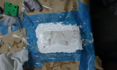
This is the original piece of outer skin that was glued back into place with 5200, on top of the new glass. After the 5200 dried, I trimmed away the excess.
Click for larger view
Overall, it came out looking OK and the repaired area was strong. During the repair, I spilled 1 drop of epoxy on the hull. I still cant get that drop off the hull, so I think that the type of epoxy I used will probably be strong enough.
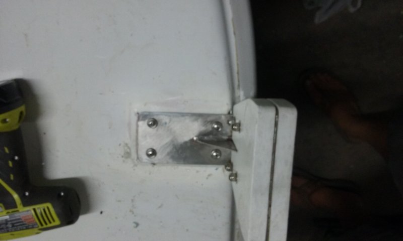
Unfortunately, the motor mount itself was now the weak point. Since it appears that the metal in the mount has been rewelded already, I figured that some reinforcement was warranted in this area. I decided to make an arm bracket that was similar to the one that Hunter used on the 170s larger cousin, the 212.
Unfortunately, the motor mount itself was now the weak point. Since it appears that the metal in the mount has been rewelded already, I figured that some reinforcement was warranted in this area. I decided to make an arm bracket that was similar to the one that Hunter used on the 170s larger cousin, the 212.

Click for larger view
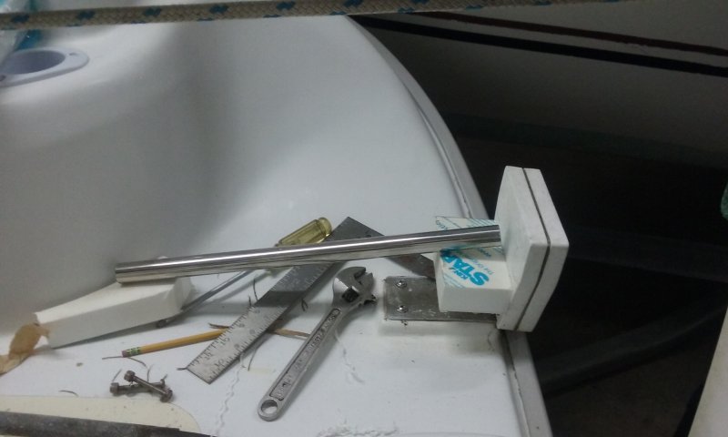
The materials I used were 18 inches of 1 inch diameter stainless bow rail and some thick chunks of Starboard.
I machined the block that attached to the motor mount and screwed it on with a pair of 1/4-20 stainless machine screws that had well over an inch of engagement in the threaded block of Starboard.
I hand filed and fit the block on the other end of the stainless tube to match the curvature of the boats molded seat.
Click for larger view
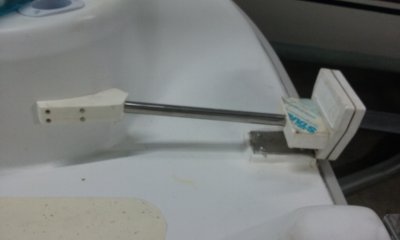
This is the semi-finished bracket. It still has not been cleaned up nor had some corners cut off, but the basic idea is there and at this point, it was structurally solid. There was no more perceivable forward to rear flex left in the bracket. I was still able to flex the bracket from side to side with a motor mounted, but since the motor does not normally produce serious stress in that direction, so I think that it is going to be OK.
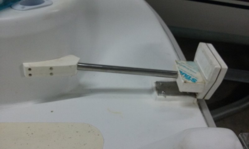
While I was beefing things up, I also took the opportunity to mill a shallow pocket on the surface that the motor clamps to. The recessed pocket will keep the pinch clamps from being able to slide sideways. This should greatly reduce the chances of the motor falling off. I do not know why all motor mounts are not made with a retention pocket like that.
#10 stainless self tapping screws mount the curved piece of Starboard to the hull. #10-24 stainless machine screws mount the Starboard to the 1 diameter tube. The tube is tapped to accept those machine screws. The tube sits in bores that are more than 1.5 inch deep. Its a pretty snug setup.

Click for larger view
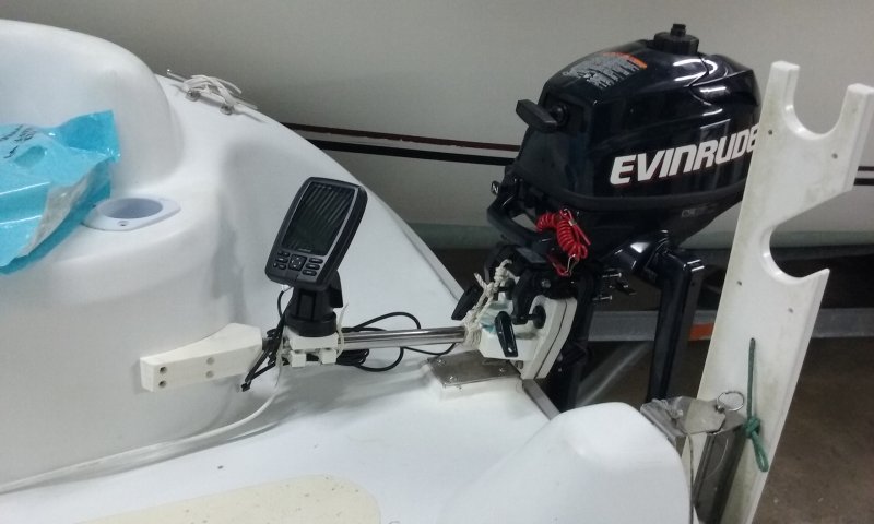
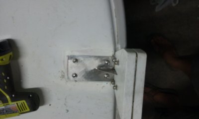
This is the finished product. As a bonus, I was able to use the 1 tube as a mounting point for my little portable chart plotter/depth finder. I share that instrument between a few small boats and I also take it with me as a back up, when I make deliveries on other peoples boats.
If I ever want to get rid of the support arm for any reason, it is just a matter of removing a few screws and plugging up 6 small screw holes with 5200. I think that I am going to keep it, unless I decide to remove the whole motor mount someday. That is not likely to happen anytime soon.
If I ever want to get rid of the support arm for any reason, it is just a matter of removing a few screws and plugging up 6 small screw holes with 5200. I think that I am going to keep it, unless I decide to remove the whole motor mount someday. That is not likely to happen anytime soon.